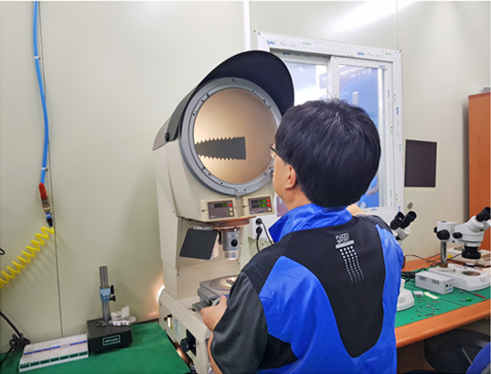
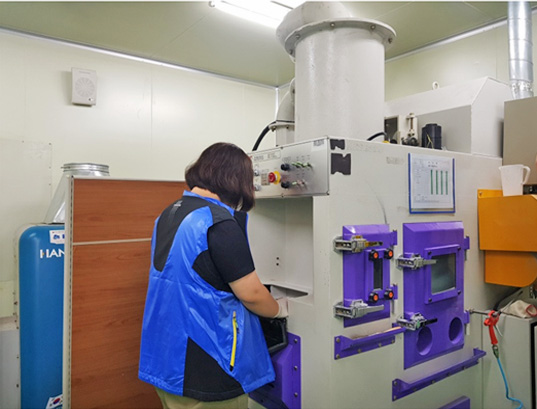
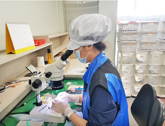
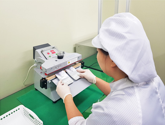
Scientific, systematic research
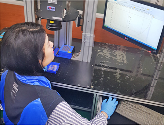
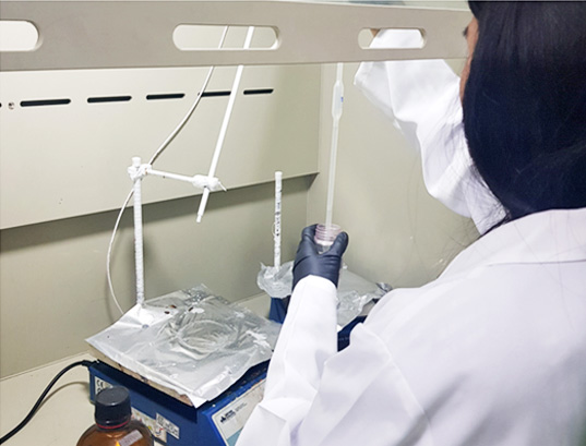
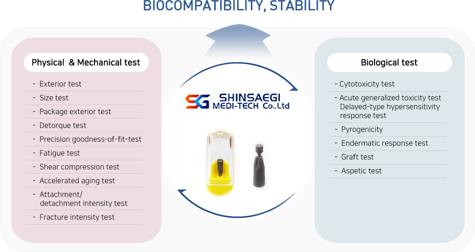
SG Implant is verified for its biocompatibility and safety. Furthermore, it has been verified for its safety by domestic and foreign institutions through biological, mechanical tests based on its surperior degree of cleanliness and precision.
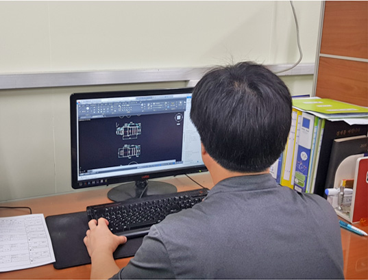
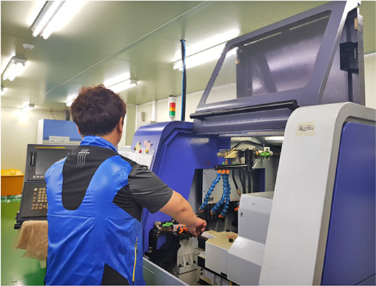
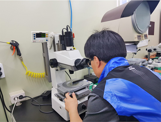
Scenery of SG Meditech research institute
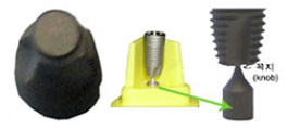
HM System (Hold Mid-air system)
- HM System presents the most safe and convenient design among packaging methods.
- The knob in the lower part of the fixture makes the fixture float on air.
- It is safe and hygienic as the fixture does not touch any part of the package ampule.
- Fixture can be easily and quickly separated from the ampule.
- The knob of the fixture is cleanly cut off after separation
Un-Packing protocol
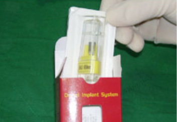
Fig1.
Remove contents from the implant packing box
Remove contents from the implant packing box
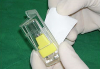
Fig2.
Peel back the tray lid expose the implant
Peel back the tray lid expose the implant
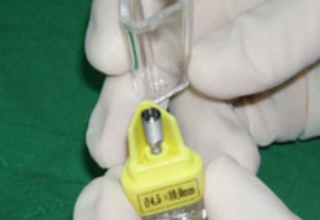
Fig3.
Draw open a cover of the implant ampule.
Draw open a cover of the implant ampule.
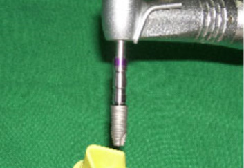
Fig4.
Pick-up the implant from the implant ampule using mountless fixture mount driver
Pick-up the implant from the implant ampule using mountless fixture mount driver
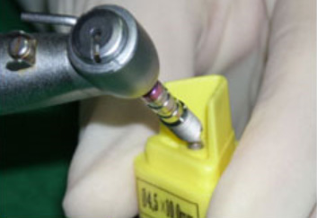
Fig5.
Break off a knob of the implant
Break off a knob of the implant
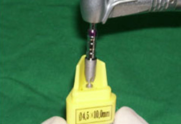
Fig6.
Insert in insice the implant using mountless fixture mount driver
Insert in insice the implant using mountless fixture mount driver
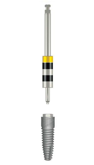
Fixture Mount Driver System
- Micro Tip is installed on the lower part of the Fixture Mount Driver to present soft and strong coherence.
- 2. Mount driver can be softly separated within mouth even after grafting fixture with strong torque.
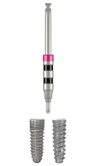
- 3. It is classified into 3 types according to fixture.
- External Hex Type (N, R, W)
- Internal Octa Type
- Submerged Internal Hex Type
- Branemark, 3i compatibility
- ITI compatibility
- ASTRA compatibility
Submerged Internal Hex Type
(SST&SRT)
(SST&SRT)
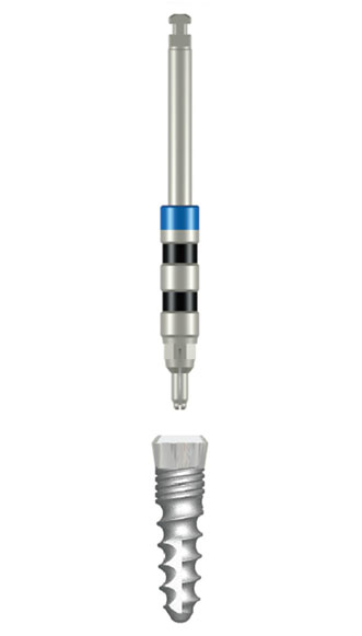
Internal Octa Type
(IT)
(IT)
External Hex Type
(EST)
(EST)
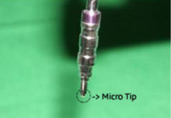
Fig1.
Intall Micro Tip in lower part
Intall Micro Tip in lower part

Fig2.
Fasten Mount Driver in Fixture
Fasten Mount Driver in Fixture
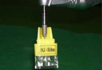
Fig2.
Strong clamping force for lifting ampule
Strong clamping force for lifting ampule
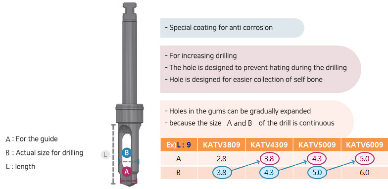
Hole Drill design
Hole Drill structure